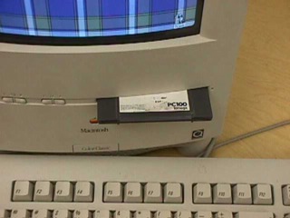
If you have an IDE-based Zip that you wish to install in a Takky, keep in mind that you can have only one IDE device, so you will need to use a SCSI hard disk. Your harness might not have a SCSI cable on it already, in which case you might still want to read the following section. Otherwise, you can skip to Part Two.
The Colo(u)r Classic wiring harness is made to handle only one internal SCSI device. To have a SCSI HD and a SCSI Zip, you will need to adapt the wiring harness by removing the one-connector ribbon, and replacing it with a two-connector (at least) ribbon.
It might be best to install the Iomega drivers beforehand, though they are included as part of later Mac OS installations.
To begin, you will need to get the wiring harness out of your CC. Remove the analog board from the "chassis" which contains the drives and logic board. You'll need to fully remove the harness from the CC in order to accomplish the re-wiring. The directions for doing this are available on pages 4, 5, and (the top of) 6 of Eric Neumann's Hi-Res mod.
Remove the metal shielding surrounding the chassis, by popping out each rectangular tab along the top of the chassis. Be careful: the shielding is very sharp and draws blood easily.
Flip the chassis over and you should be able to see how the harness is attached. Unplug all the ribbon cables from their respective plugs and unscrew the two small screws in the volume/brightness control PCB in order to free the analogue board ribbon and connector.
Carefully bend back the plastic spring clips on the chassis that hold in the LB and AB connectors and slide the harness out of the chassis.
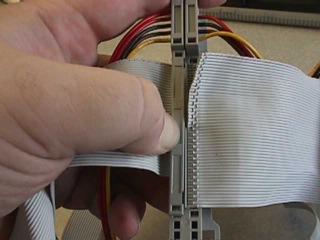
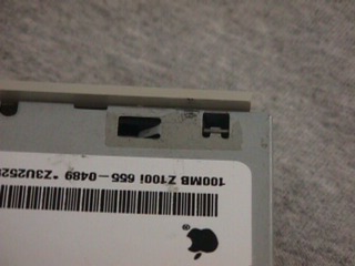
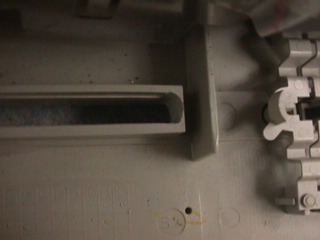
Now you need to take the one-connector SCSI ribbon off of the harness. Start by taking the clip that holds the ribbon to the harness off. Gently pry the clip's tabs out of the back of the harness with a flat head jewelry screwdriver or similar tool. They'll come partway out and then catch again; don't force them but rather gently pry them aside a second time. If you force them, you might break them. Once the clip is off, very carefully peel back the ribbon cable to remove it.
Next, take your new long multi-connector SCSI ribbon and remove an end connector (leaving at least 2 connectors on the ribbon). The end you should remove is the one with the key-tab pointing away from the ribbon. It is important to cut off the correct end. If you are looking into the holes in the connector, the key-tab should be up, and the red stripe on the ribbon should be on the bottom left side.
An easy way to make a straight cut across the end of the ribbon, with the least wasted ribbon, is to pop off the connector clip, peel the ribbon off the connector, and cut along the dotted line left by the connector's pins.
Now line up the pins on the harness with the ribbon cable, making sure not to leave too much ribbon between the pins and the raised center of the harness.
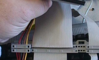
Once the pins are lined up with the wires in the ribbon, you need to press the ribbon down so that the pins puncture the plastic part of the ribbon and make contact with the wires inside. This can be tricky and if you aren't careful you can easily break the clip. A stiff rubber eraser works well to start the pins through the ribbon cable, after which the clip can be replaced and you can gently use a pair of pliers (or a soft-grip clamp) to finish the crimping.
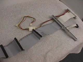
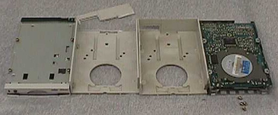
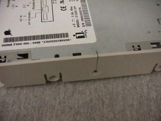
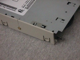
Make certain the clip is well seated. You now have a harness that will connect to more than one SCSI device. Attach a "Y" power connector with a large HD power connector and the smaller (PC floppy) power connector. Your finished harness should look something like this:
Re-install the harness in the chassis before proceeding to the next step.
The Zip drive will fit into the CC chassis with a few modifications. A Zip drive is longer than a standard floppy drive, so the CC's floppy drive sled will need to be altered. The Zip drive's faceplate/dust-door makes it sit too far inside the CC, so it will need to be removed. The Zip drive doesn't sit as high in the sled as a floppy drive so it will need to be raised a bit, and new securing holes will need to be drilled in the sled.
First you need to remove the floppy drive sled and floppy drive. Save the four brass screws that secured the floppy drive; you'll use them later.
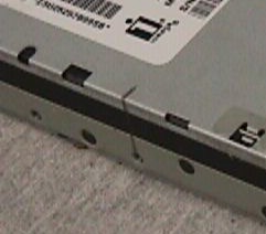
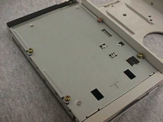
The Zip drive is too long to sit in the floppy drive's stock sled, because there is a back to the sled. Using a sharp knife, fine-toothed saw, or cutting wheel, cut the back out of the sled. Be careful not to remove the tab on the bottom of the sled that locks it into the chassis.
Screw the four brass screws that you removed from the floppy drive all the way into the bottom mounting holes of the Zip drive. This will make it sit at the proper height in the sled.
Remove the Zip drive's faceplate/dust door by pressing in the two plastic lock clips on the sides. Don't worry about losing the eject button on the Zip's faceplate. There are (at least) two versions of the Zip drive. If yours has the illuminated (clear) button, pull the entire clear plastic shaft straight out.
Use a ruler to mark the position of a side mounting hole on the top of the Zip drive. Measure how far down the side the hole is.
Put the unsecured Zip drive into the floppy sled, lock the sled into place in the chassis, and snap the chassis back onto the front of the CC. Slide the Zip drive forward in the sled until it touches the inside front of the CC, and use a pencil to mark that position on the top of the sled and Zip drive. This will show you where in the sled to position the Zip drive for mounting.
Take the chassis back off of the CC, and the Zip and sled off the chassis. Line up the pencil marks so that the Zip Drive is positioned the proper distance forward in the sled.
Using the mounting hole position mark on top of the drive, measure down the side of the sled to where the mounting hole will be, and drill the hole. Make this hole oblong tall, so the height can be adjusted if necessary. This works best on the side of the sled which is closer to the hard disk; there is more clearance there.
Use another mounting screw to secure the Zip drive to the sled.
Put the sled back into the chassis, and the chassis back into its shielding. Check to make sure the shielding clears the top of the Zip drive. If not, you may need to trim it a bit.
Attach all the ribbon and power cables. If you want to check to make sure everything is attached and working properly, snap in the chassis, put the mobo back in, plug in the power and keyboard and turn it on. Use SCSIProbe, Iomega Tools, or something similar to make sure the (empty) Zip drive is recognized. Then disconnect the power and keyboard and remove the chassis again.
All that is left to do is to make room in the CC's faceplate floppy disk hole for a Zip disk to fit. The hole is just the right height to allow a Zip disk through, but it is too narrow. The hole needs to be about 1/16 inch (1.6 mm) wider on each side to accomodate a Zip disk.
Take the chassis off of the CC's faceplate and put the chassis (especially the now dust-door free Zip drive) far away from the plastic dust you are about to create.
You may find the faceplate easier to work with without the CRT and analog board attached. If you do not wish to go to the trouble, you can skip this step, but be very careful with your sharp tools around the analog board and CRT wires.
Taking the CRT/analog board off of the faceplate is a matter of removing the four Torx screws from the corner braces of the tube and carefully removing the microphone from the clips that hold it to the faceplate. The microphone is snugged tightly into its mount with a black rubber sleeve. The rubber sleeve needs to come out with the microphone.
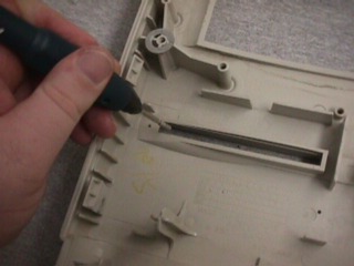
Use a grinder, drill, file, or very sharp knife to begin widening the floppy disk hole on the face plate. Neatness counts. The Zip drive sits in the same sled as the floppy drive did, so their center points should be the same. Widen both sides of the hole equally, to keep the center point the same. Be very aware of the thickness of the plastic on the hard disk side of the hole. If you take away too much you may be upset with the look.
Keep testing the Zip disk in the hole. You want to have complete clearance, so that the disk can travel effortlessly straight through the new hole. When the disk travels easily through the hole, reattach the chassis and test the fit.
At this point, further adjustments and fine tuning will need to be made. The Zip drive may sit too high or low in the sled, or the hole could need to be widened in either direction. The spacing screws can be used to adjust the height of the drive — simply loosen them slightly to raise the drive up.
If you need to widen the hole, remember that you should always take the chassis off (or at least remove the Zip drive) before creating any plastic dust.
Remember that the disk needs to travel without rubbing all the way in, or you'll have to take the CC apart to get it back out. The Zip drive's eject spring is too weak to overcome even the lightest rubbing on the casing.
If you're feeling particularly ambitious, you could use a tiny little drill bit and try to precisely line up a manual eject "paperclip hole." It would be nice — in fact, very desirable — to have the ability to manually eject a disk without taking the whole CC apart.
A very special thanks goes out to Al Miner, who first performed and documented this modification. Please e-mail both of us with any questions you might have.
Last modified on 27 Mar 2002
edited by Chris Lawson
Return to index