The yellowing on the CC isn't as bad as it looks in that picture; my digital camera tends to accentuate blue hues more than it ought to and thus the 575 back panel looks whiter than it really is.
This whole thing started when I got an LC575 board thanks to Jeff Heflin. I put it in my CC but I — like most other people — knew the original back panel wasn't going to fit. Well, I wasn't happy about that big hole in the back of the Mac, so I decided I'd do something about it. I've done a bit of work with my Dremel on stuff like this before, so I decided I'd start hacking up the 575 back panel Jeff sent me. (The stock 575 panel is way too big for the CC's panel opening.) To view any picture as full-size, just click on it.
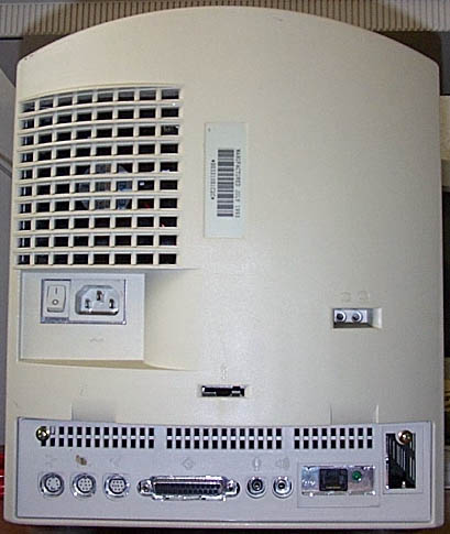
For starters, here's a picture of the whole CC with the new panel in place:
The yellowing on the CC isn't as bad as it looks in that picture; my digital camera tends to accentuate blue hues more than it ought to and thus the 575 back panel looks whiter than it really is.
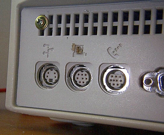
Here are a couple close-ups of the 575 panel in the CC:
 |
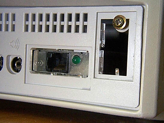 |
| Left side of panel — the small plastic divider between the upper and lower rows of holes had to be removed to accomodate the screw to hold the panel in place. | Right side of panel — note that I had to remove the Comm Slot cover in order to install the screw to hold the panel in place. |
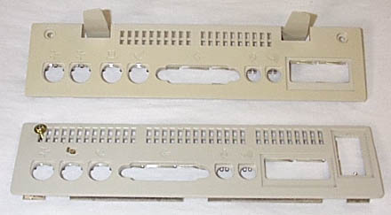
This is a comparison between the original CC panel and the new 575 panel, with the 575 panel on the bottom:
 |
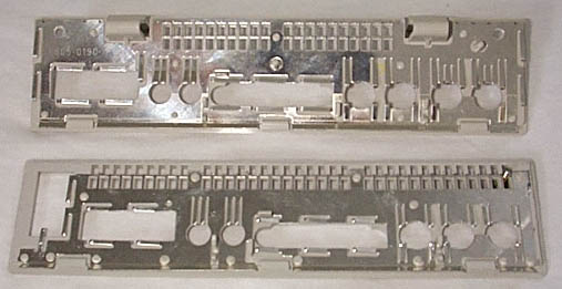 |
| Panels from the front | Panels from the back |
Here's a pic of the back of the panel:
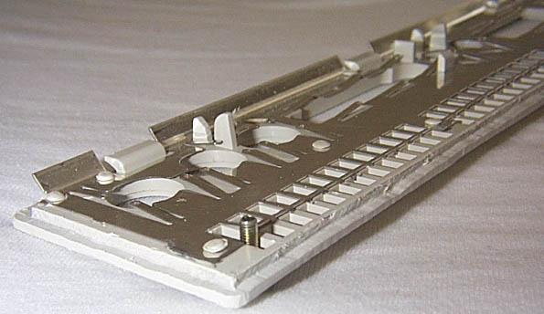
Note the lip I had to cut around the edge and the shielding removed from the top half of the top row of holes.
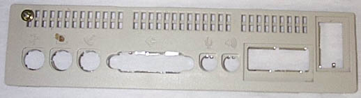
Here are the front and back of the 575 panel by itself:
 |
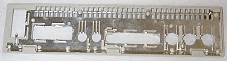 |
| Front of new panel | Back of new panel |
This is a close-up of the shielding around the Comm Slot hole:
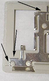
Black arrows indicate where the shielding should be cut and removed.
Another close-up of the shielding around the Comm Slot hole:
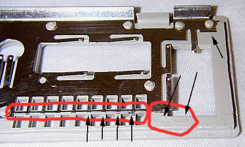
The topmost black arrow indicates a necessary shielding cut. The two black arrows in the red circle on the right indicate where two small plastic pieces have been trimmed flush. The long red circle and associated arrows highlight where the shielding was cut to remove the excess.
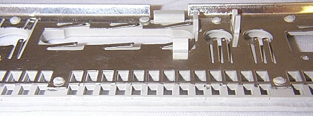
Here are a couple more shots of the trimmed shielding:
 |
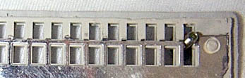 |
Here's a close-up of the lip and nearby shielding:
Note the black arrows indicating where the lip was cut out and where shielding was cut
Note that using a Comm Slot Ethernet card will require some more slight modifications to the chassis, so if you plan on using a CS Ethernet card, you'll need to remove the HD power cable cord guide. It's on the top of the motherboard bay, over on the right side. The chassis is inverted in this picture, a close-up of where the cord guide has been cut away and the hole enlarged (so that the cable can still be held up out of the way by running it through the hole).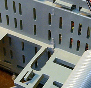 It will also require slight modification to the CS card itself; you'll need to first line up the card in the chassis to determine where to cut. Once you've determined where you need to cut in order for the screw to fit, remove the metal plate on the end of the card and file or Dremel out a small section so that the screw won't be blocked by the plate. Replace the plate on the card and reinstall the card on the motherboard and the motherboard in the chassis. Repeat trimming if necessary until desired results are achieved.
Here are a few tips on doing the conversion yourself...
Last modified on 14 Aug 2001
by Chris Lawson
Return to index